Introduction
Once the spacecraft is in orbit around Jupiter, the use of NASA’s Deep Space Network (DSN) [1] for telecommunications between the orbiter and Earth is assumed. The DSN has three stations placed approximately 120 degrees apart from each other which enables the network to cover the majority of deep space (greater than 2,000,000 km from Earth). The DSN antennas are limited in elevation coverage, but since Jupiter’s orbit is only inclined about 1.3 degrees compared to Earth’s orbit, elevation scan limitations are not of concern to this mission. Each DSN station has one 70 m dish antenna and multiple 34 m antennas. The following analysis will take both into consideration.
Downlink (Mother Ship to Earth)
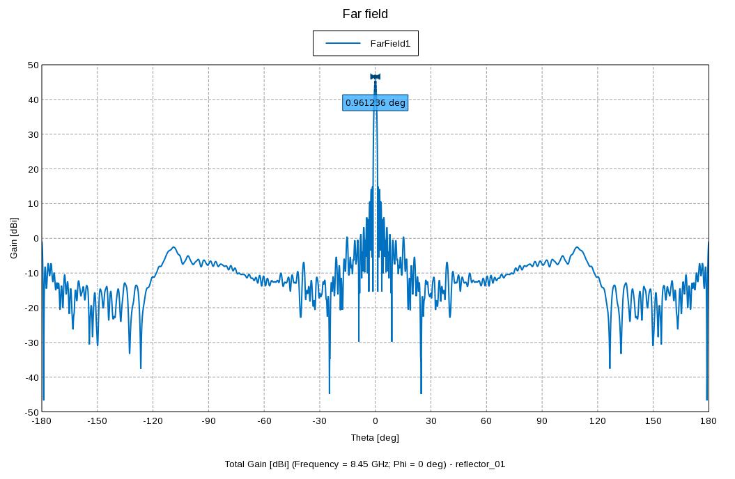
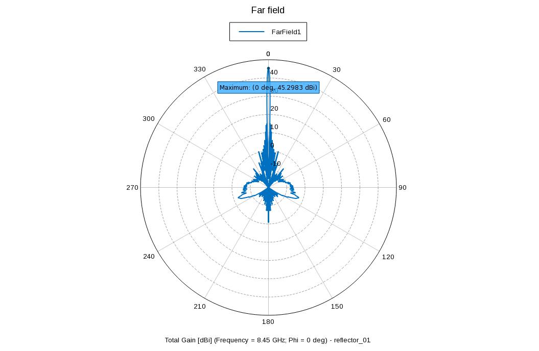
After analyzing the link design, it is apparent that the downlink is much more difficult to design compared to the uplink mainly due to the power and weight limitations of the satellite. Because of this, the Earth station that was chosen was the 70 meter dish antenna and receive system. Much of the receive path is cryogenically cooled, which makes the operating temperature of the system only about 18 K. The next decision to be made is the modulation scheme to be used and the acceptable bit error rate (BER). This design uses BPSK and a BER of 6.77e-6. Using turbo codes for forward error correction, the Es/N0 required is 1.4 dB. This is an 8.3 dB performance improvement of straight BPSK, which requires about 9.75 dB Es/N0 to achieve the same BER. The antenna was chosen to be a 2.5 meter dish antenna. This antenna will provide about 47 dBi of gain while still fitting into the payload diameter of the launch vehicle. See Figures 1 and 2 for a Cartesian and Polar plot of the antenna pattern.
Once the spacecraft is in orbit around Jupiter, the use of NASA’s Deep Space Network (DSN) [1] for telecommunications between the orbiter and Earth is assumed. The DSN has three stations placed approximately 120 degrees apart from each other which enables the network to cover the majority of deep space (greater than 2,000,000 km from Earth). The DSN antennas are limited in elevation coverage, but since Jupiter’s orbit is only inclined about 1.3 degrees compared to Earth’s orbit, elevation scan limitations are not of concern to this mission. Each DSN station has one 70 m dish antenna and multiple 34 m antennas. The following analysis will take both into consideration.
Downlink (Mother Ship to Earth)
After analyzing the link design, it is apparent that the downlink is much more difficult to design compared to the uplink mainly due to the power and weight limitations of the satellite. Because of this, the Earth station that was chosen was the 70 meter dish antenna and receive system. Much of the receive path is cryogenically cooled, which makes the operating temperature of the system only about 18 K. The next decision to be made is the modulation scheme to be used and the acceptable bit error rate (BER). This design uses BPSK and a BER of 6.77e-6. Using turbo codes for forward error correction, the Es/N0 required is 1.4 dB. This is an 8.3 dB performance improvement of straight BPSK, which requires about 9.75 dB Es/N0 to achieve the same BER. The antenna was chosen to be a 2.5 meter dish antenna. This antenna will provide about 47 dBi of gain while still fitting into the payload diameter of the launch vehicle. See Figures 1 and 2 for a Cartesian and Polar plot of the antenna pattern.
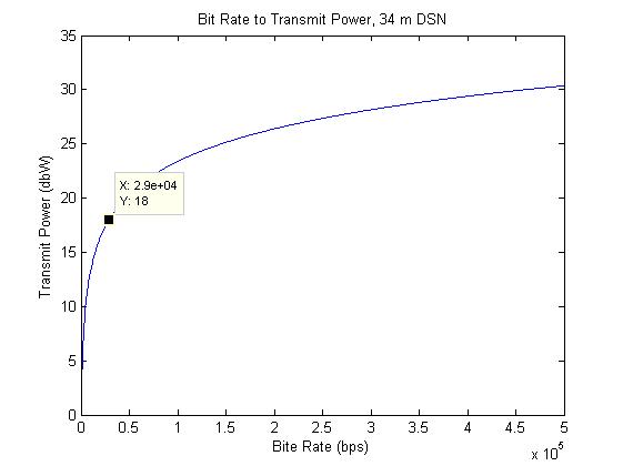
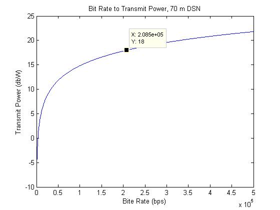
Because of the limitations of the effectiveness of solar panels at such vast distances, transmit power comes at a high premium, therefore a reasonable value of 63 W (18 dBW) was selected. The bandwidth of the system is effectively set by the previous parameters since all other variables are dependent on the Earth station. The bandwidth and bit rate of normal BPSK are equivalent, but with the use of a rate 1/2 Turbo Code one bit out of every two is redundant. Figures 3 and 4 show how the bit rate increases as a function of transmitter, all other parameters being equal, for both the 34 m dish antenna and receiver and the 70 m dish antenna and receiver, respectively.
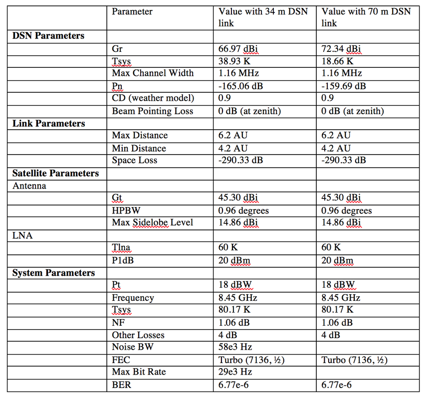
The link budget analysis was performed with the antenna pointing to zenith and a 90% weather model. A cumulative distribution (CD) of 0.9 (90%) means that weather conditions do not occur more than 10% of the time and corresponds to very cloudy conditions, but no rainfall. Below is a table showing the link budget parameters.
Table 1. Satellite to Earth Communications Specs
Table 1. Satellite to Earth Communications Specs
Cubesat to Mother Ship
In addition to the downlink, we also looked into uploading data from the CubeSat orbiters to the main Mother Ship.
The CubeSats are limited to a smaller antenna. In our case, we chose a 76 mm antenna (with a gain of 8 dBi) so
that it would fit well within our small satellite[3].
The link was designed for what would likely be a "worst case" transmission distance: the Mother Ship and the
orbiters form a 90 degree angle from the center of Jupiter, about 197,242 km which is drawn from arbitrary
potential candidates of orbital distances around Jupiter. Transmissions can occur when the satellites are even
further apart, but transmission to the Mother Ship at every possible point is not necessary. The Mother Ship will be fitted with an additional antenna for the purposes of inter-satellite communication. An antenna as large as the satellite to Earth downlink is not necessary, but we still recommend a relatively large one with a 1.6 m diameter. The CubeSats will provide 3 Watts for transmission to the Mother Ship.
Reference:
[1] Jet Propulsion Laboratory, "DSN Telecommunications Link Design Handbook," TMOD no 810-005, Rev. E, 2000. Available: http://deepspace.jpl.nasa.gov/dsndocs/810-005/
[2] Jet Propulsion Laboratory, Deep Space Communications and Navigation Systems Center of Excellence, "Juno Telecommunications," DESCANSO Design and Performance Summary Series, Article 16, October 2012. Available: http://descanso.jpl.nasa.gov/DPSummary/Juno\_DESCANSO\_Post121106H--Compact.pdf
[3] Clyde Space. (2014). *S-Band Patch Antenna* [Online]. Available http://www.clyde-space.com/cubesat_shop/communication_systems/302_s-band-patch-antenna
